Downhill Transport Of Limestone
Page - 2 - (continued)
3 Description of the whole system
The conveying route, about 2.645 m long within the plant, has to be negotiated between the crusher and the transfer station to the downstream conveyor. The average conveying capacity reaches approximately 800 t/h. The dimensioning of the conveyors has nevertheless been calculated under consideration of the conveying peaks, which can reach up to 1.400 t/h.
3.1 Tubular belt conveyor
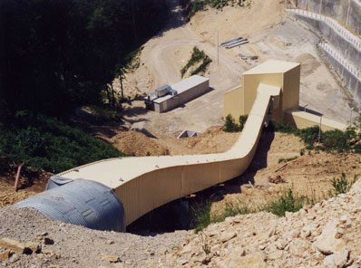
The first section of the conveyor has been designed under consideration of the extremely difficult topographic conditions from the quarry down to the intermediate valley. As shown in Fig. 1, the conveyor has to override an altitude difference of 81 m on the short distance of 242 m. This is the ideal application for a tube belt conveyor, with all following advantages:
- The ability to negotiate curves allows the best possible adaptation to the ground profile
- The very good sealing due to the tubular shape of the belt and thus the almost dust free transport of the limestone.
- As the material is supported the closed tubular belt conveyor is able to realize large angles of climb and tilt.
3.1.1 Conveying route
A troughed belt conveyor (inclined by 12°) conveys the material on the short distance between crusher and tube belt conveyor. The belt is formed into a tube immediately after the feeding point (nom. diameter of the tube 400 mm).
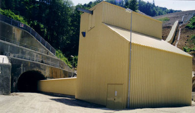
Immediately after having taken its tubular form the conveyor enters an approx. 100 m long tunnel through the top of the hill. A look into the tunnel shows (Fig. 2) that, in spite of the narrow diameter of 3.140 mm, the very compact design of the belt conveyor has made possible the installation of a maintenance catwalk.
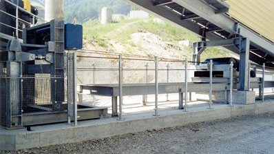
Coming out of the tunnel the tube belt conveyor follows the ground profile and reaches, in this part of the route, its max. slope of 28°. Three vertical curves with a radius of 120 m each make possible this adaptation to the local topography. At the end of 242 m of transport the tube belt conveyor passes into a trough shape before the limestone is transferred to the troughed belt conveyor with horizontal curves.
Continued on page - 3 -
Fig. 2:
Tube Conveyor in tunnel
Attachments
■
Downhill Transport Of Limestone
Page - 3 - (continued)
3.1.2 Design features
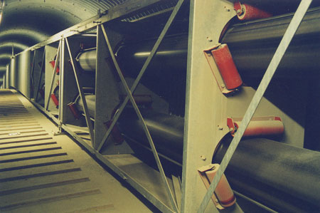
The design of the tube building section is extremely important as gentle handling is of significant relevance for the useful life of the belt. Perfectly arranged idlers and finger rollers are responsible for the controlled closing process of the belt, which needs different lengths, depending on the belt. The trouble free operation is ensured in this section by steady monitoring of the tubular form and of the filling level.
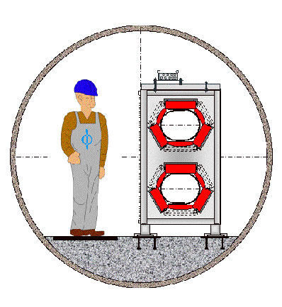
The idlers supporting the belt are mounted to the idler fixing plates which are used as supports to the conveyor. As shown in Fig. 3 the idlers are positioned in such a way that the tubular form is shaped into an oval. The flat support surface of the bottom area improves the quality of the belt tracking and the tightness of the system. In order to avoid a deterioration of the belt edges the idlers are arranged in such a way that two contiguous idlers are always overlapping on two levels. This design guarantees that, in case of tracking-off, the belt edges remain controlled and run on the next idler, without touching the end wall of the idler.
The belt itself is made of components which have proven their fitness for a use in belt conveyors over a long period of time. The arrangement of the traction elements in the belt allow its proper closing together a constant distribution of the belt tension forces.
The intelligent design of the conveyor framework and the repartition of the idler fastening plates make it possible, in the bridge areas, to integrate the conveyor frame in the metallic structure and to use it as part of the supporting structure. Weight and costs of the necessary steel works can be reduced.
Continued of page - 4 -
Fig. 3:
Idler Configuration for the BEUMER Tube Belt Conveyor
Attachments
■
Downhill Transport Of Limestone
Page - 4 - (continued)
3.2 Troughed belt conveyor with horizontal curves
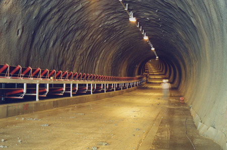
As already mentioned above, more than 2 km of the approx. 2,4 km long troughed belt conveyor with horizontal curves are integrated into a service and transport tunnel. Fig. 4 shows that, due to the local geological situation, the slope in the tunnel reaches approx. 5°.
Continued on page - 5 -
Fig. 4:
Troughed Conveyor Belt in Tunnel
Attachments
■
Downhill Transport Of Limestone
Page - 5 - (continued)
Within the tunnel, the belt conveyor is positioned along the right wall of the tunnel in conveying direction so that there is enough place left for transport and service track. The horizontal and vertical troughed belt conveyor has been designed for its max. conveying capacity of 1.400 t/h and fitted with a 1.200 mm wide belt. As mentioned in the technical data mentioned on table 2 the conveyor has to negotiate an altitude difference of -193 m, on a total length of 2.400 m. Five horizontal curves and three vertical curves enable the ideal fitting of the conveyor to the routing of the tunnel.
The conveyor is able to negotiate curves. BEUMER has developed a comprehensive program for calculation and simulation of such horizontal belt conveyors with curves. BEUMER engineers used the know own gained in numerous similar installations of the last 50 years to deepen and optimise the theoretical basic knowledge. This basic knowledge allow to calculate exactly the positioning and adjustment parameters of the idlers, according to their respective location. Variables such as the friction coefficient between idlers and belt etc. have of course been taken into account. Theoretical and practical loading situations and functions, stationary operation, start-up and shut down situations etc. have been calculated and simulated. The conditions of an emergency stop –in case of power failure at partial loading, for example- had to be particularly considered for such a descending installation. The interaction of the idlers, the drive and the brake system must ensure a secure guiding of the belt.
The drive and take-up concept for both conveyor types, the tube belt conveyor and the troughed belt conveyor with horizontal curves, will be described in the next paragraph.
4 Drive and take-up concept of the limestone transport system
Dimensioning the drive and take-up system and defining the control logic depend – beside on the above mentioned calculation - on customer’s requirements regarding reliability and profitability.
The aim of this calculation is the choice of a drive and take-up system which enables to keep the tractive forces on the belt as low as possible. The belt forces necessary to transmit the required drive power must –in spite of the low take-up forces- nevertheless keep maintained.
BEUMER has opted for a solution with a distributed force concept, combined with a take-up system according to the principle of a “constant centre distance”.
4.1 Drive concept of the belt conveyor systems
The requirements to the drive and take-up system of the troughed belt conveyor have led to a distribution of the peripheral forces on two drive pulleys at the loading station of the installation. Furthermore, the drive pulley mounted in the front and in conveying direction is equipped with two drive units.
As one of the customer’s request was to employ the same parts for both types of conveyors in order to reduce the necessary quantity spare parts on stock. Consequently one type of drive unit has been taken for both the troughed belt and the tube belt conveyor. The result is a drive pulley with two drive units at the loading station of the tube belt conveyor too.
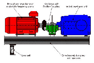
These drive units (Fig. 5) consist of a three-phase asynchronous motor with frequency control, a shat mounted helical bevel gear unit and a disc brake on the input side of the gear unit. To determine the drive torque the drive brackets are supported by a load cell. The disc brake is at the same time blocking brake and emergency brake by power failure for example.
The motors with a nominal capacity of 160 kW each, which are used for driven and driving operation, offer a wide range of regulation possibilities and enable the adequate load distribution on the various drives for different operating conditions. This means that, on stationary operation, the load is the same for all drive units even in case of a possible expansion slippage. The same applies for example if, due to variable fouling or abrasion degrees of the drive pulley coating, the drive units run at slightly different speed. A frequency converter ensures an optimum behaviour of the system during start-up. With regards to a safe guiding of the belt in the horizontal curves and to the limitation of the max. tractive forces of the belt it is very important that the peripheral forces of the pulley do not exceed certain values at start-up. The peripheral forces depend mainly on the drive power demand when the conveyor is on stationary operation, whereby the power demand itself is subject to the material distribution on the conveyor.
It was therefore necessary to choose a starting-up strategy which takes into account as well the length of the installation, as its tensioning system and its routing. BEUMER developed for such applications a special starting-up and stopping system which guarantees that the proper torque is produced according to a set curve depending on the operating mode and that the transition to the stationary operation remains always smooth and without shocks. All these measures enable to reduce to a minimum the supplementary dynamic stress on the belt. The progression of the three drive torques, of the conveying speed and of the tension force during such a start-up under continuous load of the conveyor shows clearly that, due to the defined and curved progression of the torque, the tension force also remains constant and without peaks. Despite the long way (approx. 2.4 km) between the take-up station and the point of force introduction and despite the fact that the introduced force is transported to this point by a relatively elastic belt, there is no significant variations of the tension force.
Continued on page - 6 -
Fig. 5:
Drive Station with load cell for measuring the drive pulley circumferential force
Attachments
■
Downhill Transport Of Limestone
Page - 6 - (continued)
4.2 Emergency stop principle
A special feature of this kind of systems is the driving operation with continuous load. The resulting power capacity of approx. 350 kW is transferred to the public net via an energy recovery system. This reduces considerably the costs of energy of the whole system.
The driven operation of the system demands a special shut-down concept for emergency situations like power failure. As it would be impossible, in such a case, to stop the installation with the drive motors it has been necessary to install a second, redundant braking system. The torques produced by the drive motors are measured with load cells on the loose drive brackets and directly transmitted to the brake unit. In case of power failure, the brake unit generates a torque depending on the measured value, shutting down the installation within the required 20 seconds. This avoids an overload of the installation and particularly of the belt (even in emergency situations).
4.3 Take up system
The principle of “constant center distance” is applied to adjust the tension of the belts in both installations. A take-up carriage with take-up pulley is moved horizontally by an electric winch in order to regulate the required pretension (Fig. 6). Before each start of the installation, integrated load cells measure the existing tension force, compare it with the setpoint value and eventually correct it automatically. In such a take-up system the pretension force and the drive power involve each other so that, during the time of operation, the existing take-up tension has to be compared with the due one which is depending on the drive power. This enables to compensate incorrect belt tension forces, as such due for example to belt expansions caused by temperature. Should the actual pretension during stationary operation be outside the setpoint value range, an automatic control and monitoring system will make an outside intervention possible.
Continued on page - 7 -
Fig. 6:
Take-up arrangement
Attachments
■
Downhill Transport Of Limestone
Page - 7 - (continued)
5 First practical experience with the limestone transport system
After an installation and commissioning period of less than 10 months the limestone transport installation could be handed over to the customer and the exploitation of the quarry could start. In spite of the very difficult erection conditions the widespread simulations of the belt conveyor installation, carried out in a preliminary stage, have made possible to complete the commissioning of the whole system within only 4 weeks. Tests during the commissioning period and the trial operations – particularly those simulating extreme situations like emergency stop at power failure, varying loading conditions, etc. – confirmed the calculations to full extense. The data recorded in all operating conditions and concerning the belt tensile forces, brake torque and speed variations proved in an impressive way that inadmissible belt tension forces or speed variations never occur. The redundant braking system, with a braking torque depending on the respective loading situation, has shown its ability to stop the installation in an emergency situation.
Continued on page - 8 -
Fig. 7:
Downhill conveyor
Attachments
■
Downhill Transport Of Limestone
Page - 8 - (continued)
6 Closing remarks
The here described exploitation of the Tscharner quarry is the positive proof that innovative solutions in the field of belt conveying technology are the ideal backing for a reliable and cost-efficient production. The crucial technical basis have been here the optimal combination of tubular and troughed belt conveyor together with a reliable drive concept.
Moreover the positive experience gained during commissioning show the tremendous possibilities
For more information on BEUMER, please visit:
https://edir.bulk-online.com/profile...umer-group.htm
http://www.google.com/search?client=...UTF-8&oe=UTF-8
Attachments
■

Downhill Transport of Limestone
Downhill transport of limestone
- Technology at high level for curved conveyor
Summary
The supply of raw materials is all dominant in a cement plant. The following article is dedicated to the BEUMER´s installations for limestone transport in the new quarry from Tscharner (CIMENTS VIGIER S.A.) in Reuchenette, Switzerland. The characteristics of the BEUMER equipment, a tube belt conveyor and an troughed belt conveyor with horizontal curves, are its state of the art design with an innovative drive system, permitting the adaptation to the difficult topographical conditions of the Swiss mountains.
1 Introduction
The supply of raw materials has a vital importance in cement plants where prosperity rests on a cost efficient and reliable technology. The expensive limestone transport on trucks is ecologically non acceptable and belongs to the past. The cost efficient continuous conveyors are the acknowledged way for modern solutions. They are perfectly adapted to all kinds of terrain and offer following advantages with regards to a transport on truck:
- High conveying capacity with minor space requirements
- Low construction costs of the conveyor, even in areas which are particularly difficult of access
- Low energy consumption, compared with a limestone transport on truck
- Low personal requirements
- Ideal adjustment to the local environmental conditions on site, leading to a minimisation of the environmental prejudices
- Low noise emission
Some of the new limestone deposits can only be exploited when using curved belt conveyors with horizontal curves. One main reason for the choice of this transport technology is the easier way to get the installation licensed.
The horizontal curved belt conveyor described in this article is situated in the new limestone quarry “Tscharner” in Reuchenette, which belongs to CIMENTS VIGIER S.A. Switzerland. The particularity of this special installation is a continuous conveying system between the limestone deposit on a mountain and the cement plant in the valley. The extracted products have to be conveyed downwards. The particularities of a descending material transport and the ultra-modern drive system are object of this article as well as the actual technology developments in the field of steady conveyors with horizontal curves applied in this special project.
2 Requirements on the belt conveying system
Sketch 1 shows the route of the conveying installation between the crusher, situated on the limestone quarry above the cement plant and the cement plant itself. The conveying installation has to cope with 280 m altitude difference and a slope of max. 28°. The first target to hit was to limit the amount of conveyors and to allow a restricted quantity of transfer stations. A tunnel designed for limestone transport by truck had also to be used as a part of the conveyor route. Prime aims of the project were on the one side a high reliable installation, notwithstanding the highly varying operation conditions, and on the other side to use to full capacity the energy produced by the descending conveying installation. BEUMER´s answer to this technological problem was a tube belt conveyor in the first section, followed by a troughed belt conveyor with horizontal curves for the transport inside the tunnel. The tubular belt conveyor makes possible to handle up to 1.400 tons material per hour, in spite of the 28° inclination. This type of closed conveying system is particularly appropriate to a descending route. The troughed belt conveyor, which conveying route runs along the outer tunnel walls, is the optimal solution in combination with the travel and service track within the tunnel (Fig. 1).
Following paragraphs present both types of conveyors with their technical and functional particularities. The drive concept, similar for both conveyors, will be described thereafter.
Continued on page - 2 -
Figure 1:
Conveyor Routing of the BEUMER Tube Belt Conveyor at Ciments Vigier S.A. in Reuchenette, Switzerland
Attachments
beumer-bild-1-(2) (JPG)
■