Re: Vacuum Conveying Dilute Slate
Dear Lars,
I made a preliminary vacuum conveying calculation with the following assumptions:
- particle size 1000 microns
-particle density 2800 kg/m3
-suspension velocity 6.8 m3/sec
-An assumed material loss factor.
-Given pipe geometry
Applying the given vacuum blower resulted in approx. 1 ton/hr at a vacuum of 0.4 bar with air velocities from 42 m/sec to 53 m/sec.
Applying a vacuum blower of 1440 m3/hr, the calculated capacity is approx. 6 tons/hr at 0.28 bar vacuum.
Energy consumption approx. 3 kW/ton
Your original design is too far into the dilute phase region.
We are planning to feed the slate from a conveyor belt into a hopper with a venturi pipe in the bottom to increase the speed of the slate.
Are you applying a compressor with a nozzle venturi eductor?
This should not be necessary at all. With a controlled feed, the slate is accelerated by the vacuum air mass flow.
You have the vacuum blower positioned after the cyclone.
A cyclone is not cleaning the vacuum airflow sufficiently for a positive displacement blower.
The blower will suffer severe damage of the passed dust.
The cyclone should be replaced by a self-cleaning filter. (If the slate is dry enough)
Keep in mind that my calculation is a rough estimate.
It would be very helpful, if you have installation data and performance data of other pneumatic installations, conveying this type of slate (or similar slate).
The pneumatic conveying properties can then be derived from those installations and used for future calculations (like this installation)
Considering the short distance (straight approx. 15m, a screw conveyor could also be an option.
Have a nice day
Teus ■
Teus
Re: Vacuum Conveying Dilute Slate
Hey Mr.Tuinenburg.
First of all. Thank you for your time. It is highly appreciated.
There is a small misunderstanding here. Feeding is done direct into pipeline; witch has a small hopper to guide slate into pipe from conveyer belt.
We do have 2 parallel filters between cyclone and blower. Both are self-cleaning.
How can our blower with 2600 m3/hr. only manage 1 ton/hr. when 1440 m3/hr. can do 6 tons/hr.?
Our existing system is for cleaning debris for production, and is just being used as a vacuum-cleaner around the factory. Our mission is to empty a small silo with slate, due to colour change in material.
Our Plan:
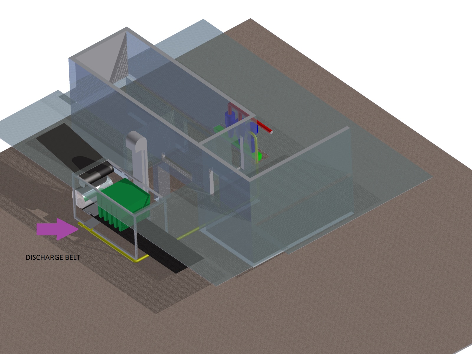
Mount additional pipe into cyclone, and program some valves that can choose between either one of them. When silo needs to be discharge, the plan is to cut out "the vacuum cleaner" and just run the pipe that is mounted under the discharge convening belt. All we need is to find out if this can be done when discharging rate is approximately 1, 67 kg/sec. Any suggestion for this setup. Our pipe diameter can be changed to lower air-velocity. We cannot change blower.
About screw conveyor options: There is absolutely no room for this option, due to installation of other equipment in factory and supporting pillars of the building construction.
I have made a small drawing about the situation. (see attached picture)
Lars.
Yellow line is what we want to install, blue is cyclon and 2 filters. Red is air to pump

href="https://forum.bulk-online.com/attachment.php?attachmentid=35967&d=1367858314" id="attachment35967" rel="Lightbox78795" target="blank">
Attachments
■
Re: Vacuum Conveying Dilute Slate
280 mbar vac is very high for 5" pipe going only 15m is extreamly high.
I estimate it to be about 60 -70 mbar vac. If you want to use a roots exhauster
then as suggested by Mr Teus you will need a reverse jet filter. Other option
will be to use side channel or fans; they can handle dust to a certain levels. Venturi in
the start is not needed just have a suitable sized fixed orifice for controlling the feed
rate into the conveying pipe this will even out the feed from the belt conveyor. ■
Re: Vacuum Conveying Dilute Slate
Dear Lars,
2 parallel filters between cyclone and blower. Both are self-cleaning.
This should be OK
How can our blower with 2600 m3/hr. only manage 1 ton/hr. when 1440 m3/hr. can do 6 tons/hr.?
This is explained by the so called Zenz diagram.
When pneumatically conveying a material, there are several partial pressure drops involved.
Amongst them are the velocity related material pressure drop, which increases with the square of the blower displacement. (At constant rate and pipe diameter and length)
Another pressure drop is for keeping the material in suspension and decreases with the velocity as the material has to be kept in suspension over a shorter period of time.
Where the sum of the pressure drops as a function of the blower volume is minimum, this lowest point in the curve is named “The Zenz point”.
At a blower displacement below this point, the pressure drop increases and the flow regime is called “dense phase”.
At a blower displacement above this point, the pressure drop increases and the flow regime is called “dilute phase”.
Your design is way into the dilute phase region (due to the very high velocities) and reducing the airflow decreases the pressure drop or makes a higher capacity possible at a given pressure drop.
Our pipe diameter can be changed to lower air-velocity.
Increasing the pipe diameter from 5” to approx. SQRT(2600/1440*5) = approx. 7” lowers the velocity and also increases the capacity. (There is more power available)
This option should be feasible as the cyclone and filters are already designed for this blower.
(Other diameters, I have to calculate. Not yet done, but can be done if needed)
Have a nice day
Teus ■
Teus
Re: Vacuum Conveying Dilute Slate
 Originally Posted by Teus Tuinenburg
Hi Mr. Tuinenburg
Please feel free to calculate which diameter I should choose for my design/configuration.
If you want, please mail me some copies from your calculations. (pdf would be great).
That would give me some data to back me up when I get confronted with this later in my project.
I really can't explain how grateful I am for the help u are giving me.
Lars ■
Re: Vacuum Conveying Dilute Slate
Dear Lars,
I calculated the system for a pipe diameter of 8”.
The result is shown in the attached file.
I have to emphasize that the real pneumatic conveying properties of the ground slate are not known and that the calculation has to be considered as an indication or estimate only.
Two of the more important key properties are the suspension velocity and the material loss factor.
The suspension velocity is estimated from the particle size and the particle density in combination with an assumed (average) drag factor.
The material loss factor is estimated by comparison with other look alike materials.
It is clear that 35 kW of available vacuum power should be sufficient for the required 6 tons/hr.
Instead of building steel pipes, a flexible 8” suction hose of approx. 15 to 20 m is also an option.
Take care
Teus
Attachments
■
Teus
My Calculation
Originally Posted by Mantoo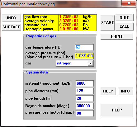
href="showthread.php?p=78796#post78796" rel="nofollow">
I am always trying to verify my software's calculations for positive pressure systems. For a gas velocity, which is by the factor 1.5 larger than that at the minimum pressure drop in dilute phase, the result matches with your estimation.
href="https://forum.bulk-online.com/attachment.php?attachmentid=35989&d=1368206145" id="attachment35989" rel="Lightbox78842" target="blank">■
Re: Vacuum Conveying Dilute Slate
Dear Manfred,
I am always trying to verify my software's calculations for positive pressure systems
This thread is concerning a vacuum system.
Therefore the pipe end pressure should be lower than 1.03E+00 bar(a) as given in your screenshot. (1.03E+00 bar(a) – vacuum)
The gas mass flow in a vacuum system is depending on the vacuum and this is the reason that only an iterative algorithm can solve the calculation of a capacity at a certain vacuum. (or v.v.)
From your screenshot:
gasflow rate = 1738 kg/hr
end pressure = 1.03E+00 bar(a), which is intake pressure vacuum pump.
gas density at 1 bar(a) and 20 degr.C =1.18
follows:
vacuum pump displacement = 1738/1.18 = 1472 m3/hr.
This does not correspond with the given displacement of 3500 m3/hr of the used Nederman RBU 2600 vacuum pump.
Looking at the manufacturer website:
http://www.nederman.com.pl/ulotki/wy...Technical.pdf
the performance curve is somewhat unclear.
Probably the curve represents nm3/hr instead of displaced m3/sec.
Also the title of Fan Diagram RBU is an unusual description of a positive lobe blower.
In my calculation, I realize now that I underestimated the blower displacement (I used 2600 m3/hr instead of 3200 or 3500 m3/sec)
Regards
Teus ■
Teus
Re: Vacuum Conveying Dilute Slate
Dear Manfred
It is good to know that my calculations match yours.
My calculations were base on an ideal system not using excessive power. They do not
not take into account the use of the existing exhauster on site. In my opinion it is
too much over sized and will just waste KW's. Actually this system can be pushed in a
4" pipe with about 900 m3/hr air flow and 160-180 mbar vac at exhauster. But most of
manufactures will not go for it due to higher risk involved.
Unfortunately it is very difficult to get site verification results on these forums so we
will never know the outcome!!!!!! ■
Re: Vacuum Conveying Dilute Slate
Originally Posted by Mantoo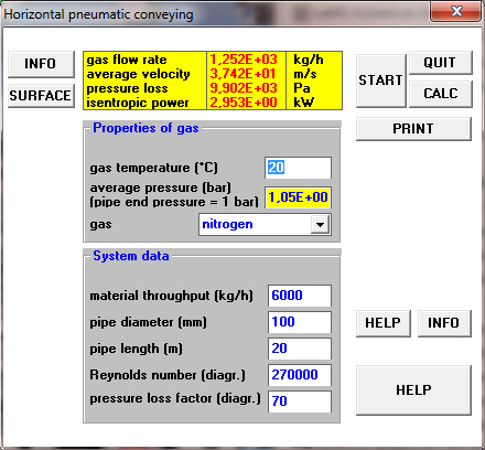
href="showthread.php?p=78850#post78850" rel="nofollow">
Dear Mantoo!
Look at the screen shot of my (positive pressure) calculation for a pipe diameter of 100 mm. The gas velocity is (because of the particle size) again by the factor 1.5 larger than that at the minimum pressure drop in dilute phase. The calculation result applies for a steady material flow. Because of the short pipe length I must add to the calculated pressure loss of 10 kPa about 6 kPa (?) for the acceleration (solid/gas Ratio = 6) of the feeded material. The result is an over all pressure loss of about 160 mbar (16 kPa).
I agree by the way completely to your remark on the verification results.
Best regards, Manfred Heyde
href="https://forum.bulk-online.com/attachment.php?attachmentid=35994&d=1368397794" id="attachment35994" rel="Lightbox78851" target="blank">■
Re: Vacuum Conveying Dilute Slate
Dear Manfred, Mantoo,
I recalculated the installation for:
4” pipe diameter
900 m3/hr = 0.25 m3/sec vacuum pump displacement.
The results are:
4.4 tons/hr at 180 mbar vacuum
and
6.0 tons/hr at 195 mbar vacuum
Gas velocity = 28 to 30 m/sec
SLR = 7
pressure drop for acceleration = 43 mmWC 0.43kPa
pressure drop for product losses = 357 mmWC
pressure drop for elevation = 39 mmWC
pressure drop for suspension = 180 mmWC
pressure drop for gas = 552 mmWC
pressure drop for filter = 628 mmWC
Power = 9.4 kW
Energy consumption per ton approx. 1.55 kW/ton
Note:
The 8” installation consumes approx. 0.46 kWh/ton at 75 tons/hr – 300 mbar vacuum
The blower choice has a major influence on the calculated pressure drop, because the pressure drop for gas and filter are already approx. 68% of the total pressure drop. A 10% airflow increase results in a pressure drop of 264 mbar vacuum (approx. +35%)
This can be expected, due to the very low Solids Loading Ratio.
Regards
Teus ■
Teus
Re: Vacuum Conveying Dilute Slate
Gents
The 900 m3/hr figure was form the top of my head. Looking at the
velocities they are bit high I think we can bring the air flow down to
650 m3/hr. This will reduce the conveying pressure further. SLR will
go up to 9 - 10. 6 tons will easily be achieved at 180 mbar vac. ■
Re: Vacuum Conveying Dilute Slate
Dear Mantoo,
Calculating the system according your design results in:
Air flow = 650/3600 = 0.18 m3/sec
4” pipeline
8.5 tons/hr at 180 mbar vacuum.
Solid loading ratio = 13.5
air velocity = 20 m/sec – 23 m/sec
Energy consumption = 0.75 kWh/ton
The sedimentation starts from and above 235 mbar.
After 12 replies we have a “communis opinio”.
Have a nice day
Teus ■
Teus
Re: Vacuum Conveying Dilute Slate
Indeed Mr Teus
We agree on this one. But after all these replies at least we have reduced the power
consumption from 3 kw/ton to 0.75 kw/ton.
Sucess!!! ■
Re: Vacuum Conveying Dilute Slate
Originally Posted by FagskolenDear Lars,
I suggest your getting a copy of my article on pneumatic conveying calculations and run these calculations your self. This will give you more knowledge than if other people run these calculations for you. Calculation method is the same for vacuum and pressure type conveying systems.
Regards,
Amrit Agarwal
Pneumatic Conveying Consulting
email: polypcc@aol.com
++++++++++++++++++++++++++++++++ ■
Vacuum Conveying Dilute Slate
Good day to everyone,
I am in a school project which i is about conveying grounded slate in a plant which produces shingle.
I must admit that i am still a novice at in vaccuum conveying, so therefore seek help from you people.
The system we are designing uses an already existing vacuum system located in the plant. We are planning to feed the slate from a conveyor belt into a hopper with a venturi pipe in the bottom to increase the speed of the slate. The system should be able to convey 100 kg/min for max 10 minutes.
The components I have available are as follows:
Pump: Nederman RBU 2600
- Shaft power: 55kW
- Q with -20 KPa: 2600 m3/h
- max Q: 3200 m3/h
- max vacuum: 45 KPa
- Present operating vacuum: -30 KPa
Pipe: Steel, "Standard" roughness.
5 metres horizontal
1 90deg bend
6 metres horizontal
1 90 deg bend
5,5 metres vertical
1 90deg bend
1 metre horizontal into cyclone
We are considering a 127 mm pipe, this was recommended by the supplier. He didn`t have any theory or empiric data to confirm this.
Material: Grounded slate
Sieving test resulted in particles fram 0,35 mm to 2 mm size, mainly 1 mm (40%)
Bulk Density: 1,280 Kg/dm3
I would like your opinion about if this is going to work.
Regards
Lars ■