
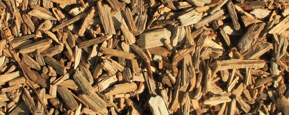
Biomass energy is derived from a wide variety of fuels: municipal solid waste (MSW), construction and demolition materials (CDM). Wood feedstocks can be quite variable from chipped virgin wood, wooden pellets, broken up pallets even chopped up door frames. As a result the biomass materials can be poor flowing and may contain foreign matter. The challenge for biomass energy companies is to feed this material at a consistent rate into a combustion or decomposition chamber, at an elevated temperature, while preventing air ingress. Plug screw feeder technology is proving to be particularly effective in meeting these conditions for continuous plant operation.
Characterisation for Flow
Like any industrial process involving bulk materials, the ease with which materials are processed is dependent upon their flow characteristics. Biomass processing is no different. Even though the range of biomass materials creates an uncontrolled variability of feed stocks, it is important to understand the flow characteristics for the biomass materials with respect to foreign bodies, size of constituent components such as lumps, and size of biomass pieces, and design biomass processing plant equipment accordingly, in order to ensure continuous operation. Assessing the flow characteristics of biomass fuels is dependent upon successful measuring the material's bulk density in loose and compacted conditions (taking into account variation with stress), shear strength and wall friction affecting hopper flow, and internal friction and permeability which influence screw feeder plug formation and effectiveness as a barrier to air ingress.
In addition, the materials will have variable moisture content, density, elasticity. These factors, and the interlocking nature of these materials, mean that the classical Jenike approach to assessing flow characteristics is often unsuitable.
| Flow property | Flow behaviour |
| Bulk density | Driving force for gravity flow |
| Hausner ratio | Ratio of tapped to poured bulk density – effect of compacting |
| Wall friction | Opposing slip on contact surfaces |
| Shear strength | Resists deformation for flow |
| Permeability | Ease with which gas flows through bulk |
| Particle size | Fine powders can arch |
| Presence of lumps | Lumps can jam screw feeder |
| Particle shape | High aspect ratios can cause ‘bird nesting’ |
| Moisture content | Changes will affect flow condition |
A better approach to determine the flow characteristics of biomass materials is to use multi-axis Spider Diagrams. These allow an assessment of biomass flow behaviour based on multi-attribute of flow sensitivity, with wall friction, stress-sensitivity of density and interlocking characteristics. interpreting the spider diagram correctly is critical to the design of hopper shape, wall slope, outlet size and screw feeder.
Powder Flow Predictability
The spider diagram takes the measured characteristics of wall friction (Φw) shear strength (τs) bulk density (ρb) and adds three further factors: hopper wall angle (βc) outlet size (Dcrit) and Hausner Ratio (H.R.). The greater the ratio the more sensitive the powder is to vibration and hence flowability worsens. Using these factors it is possible to produce a "spider" diagram comprising a series of three concentric circles are divided by axes for each of the characteristics. These axes intersect with the smallest diameter circle where that particular characteristic describes "easy flow" with subsequent bigger diameter circles defining modest' and "poor flow".
Two idealised situations can then be presented, see Figs. 2 and 3 for an easy flow material and a poor flow one with the infilled part of the "web" detailing the particular characterisation attributes.
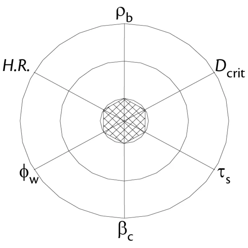
Fig. 2: Spider diagram of the idealised ‘easy flow’ material.
|
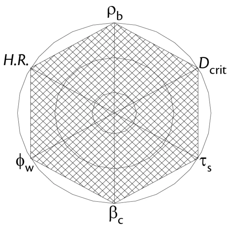
Spider diagram of the idealised ‘poor flow’ material.
|
The spider web diagrams can be more than qualitative if the data from the tests on a large number of materials is used to define the easy, modest and poor flow circles. These classic parameters are also useful for characterising biomass materials but benefit from incorporating aspect ratio of particles (L/d), moisture content (M.C.) and permeability (K).
| Circle | Wall friction [deg] | Bulk density [kg/m3] | Shear strength [N/m2] |
|---|---|---|---|
| Easy flow | < 20 | 1200 | 300 |
| Average | 25 | 800 | 1000 |
| Poor flow | > 30 | 400 | 2000 |
| Circle | Hausner ratio | Outlet size [cm] | Mass flow wall angle [°] |
| Easy flow | 1.1 | 15 | 65 |
| Average | 1.25 | 50 | 73 |
| Poor flow | 1.5 | 100 | 80 |
Analysis of Feed Stocks
The red line spider diagram for chipped wood, see Fig. 4, shows low density and high aspect ratio, indicating an ability to "bird’s nest", also large pieces will cause blockages and handling issues. Nails for example, can damage process equipment. The blue line spider diagram for shredded MSW, on the other hand, has very low density and a high Hausner ratio making hang ups likely.
Implications for Design
The implications of the spider flow characteristic analysis for hopper design are that traditional converging-shaped hoppers will often be prone to arching and that internal agitators, vibrators and air injection are likely to have limited success in promoting flow. Therefore a "live" hopper outlet using twin or more multiple screws to serve the full bottom width, and diverging walls are essential. Moreover, plane mass flow where flow is stable and steady, segregation avoided and a "first in, first out" pattern is obtained, should be promoted with radius hopper corners, preventing ratholes and "corner hangups". Flow intrusions such as misaligned joints and poorly placed level probes must also be avoided.
The feeder options for biomass include vibratory feeders which, though tolerant of lumps, do not offer positive displacement and are awkward to enclose satisfactorily. Belts and apron feeders too are not easily enclosed, and offer limited progressive extraction. In addition, neither is able to provide a positive contribution to assisting hopper flow. Screws feeders, on the other hand, possess excellent enclosure and positive displacement characteristics, but can be vulnerable to jamming with tight clearances. This can be resolved by deploying multiple screws, giving wide and long progressive extraction outlets, and eliminating hang ups. Progressive pitch and stepped shaft diameter will provide maximum "live" inflow capacity along the length of the slot. To prevent jamming in the screw clearances and shaft alignment also needs special attention.
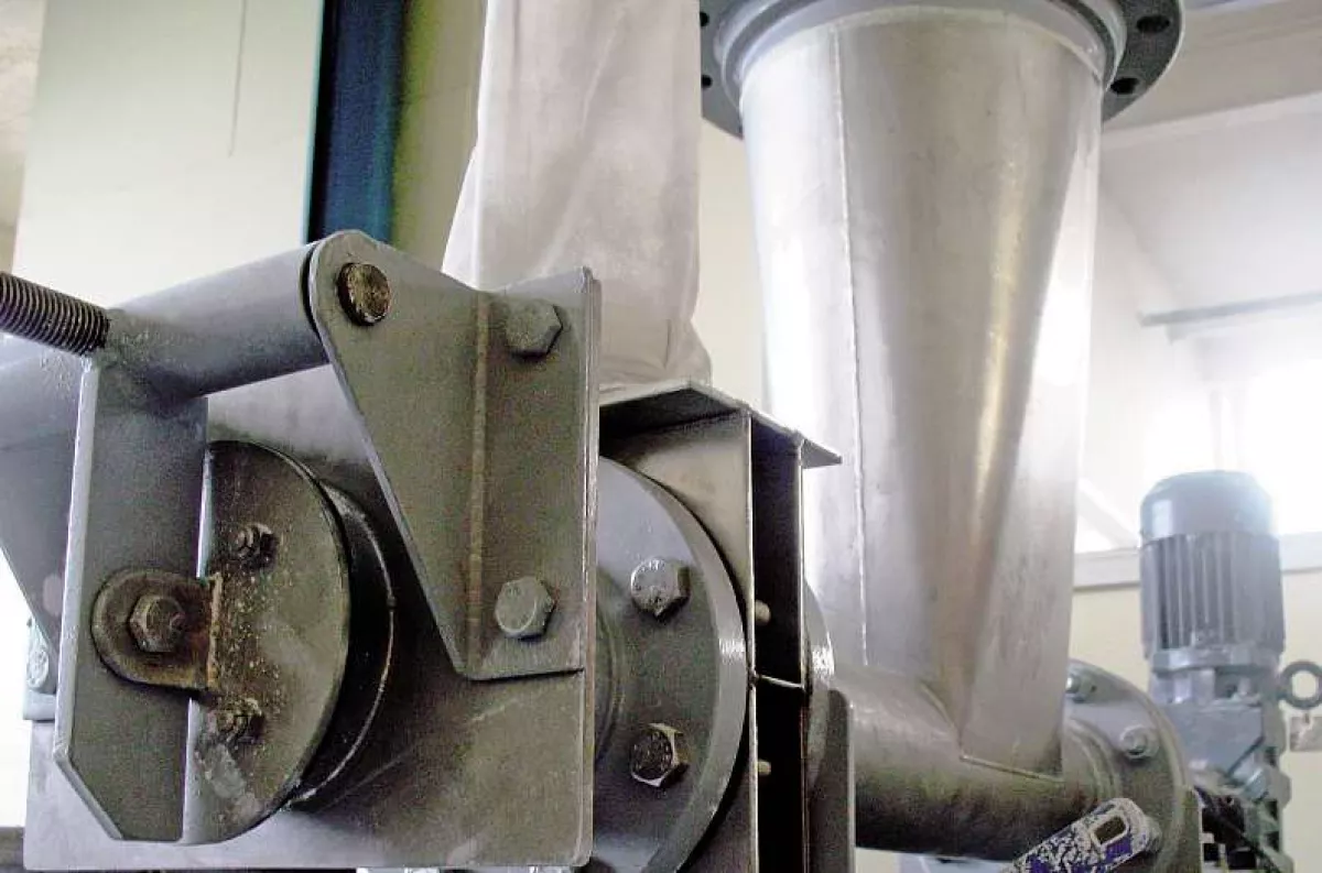
Plug Screw Feeding
A plug forming approach using a screw feeder is often preferred when feeding material into environments where there is a significant temperature or pressure differential. The plug is a controlled build-up of material created at the point where the screw enters the process, protecting the feed equipment and prior material from early exposure to high temperature and preventing ingress of vapours from the process into the screw and feed hopper.
The screw end is designed to generate maximum end force, and a balanced compacting force. The plug forms in the barrel section after the flights end and is replenished by fresh incoming material (note it does not self clear though may degrade with process conditions). A weighted flap valve can also be used to generate resistance and encourage plug formation. The screw pushes material into plug forming zone where a diverging wall generates good compression and ensures positive advance of the material.
Knowing the optimum plug length to achieve a steady flow is based on the measured flow properties of the feed material, experience and often trials. Changes in either the biomass material formulation or environmental conditions, can affect the plug performance, leading to poor screw feeder discharge and an increased risk of gas ingress through the feeder. To address these issues, and make the equipment flexible enough for dealing with a range of material and process conditions, the operator is able to adjust the length of the "plug" to match or exceed the back pressure on the plug, thus ensuring consistent discharge from the screw feeder. In so doing it overcomes the inflexibility encountered with fixed length plugs that limits their use in the processing of highly variable, biomass materials.
Plug Feeder for Ash Removal
The same plug screw technique can be applied to ash removal. In biomass gasification plant, ash is produced during the gasification which has to be removed from the gasifier. Maintaining an oxygen-free gasifier is essential. Here the plug screw feeder densifies the ash as it leaves the screw to create an impermeable barrier, allowing the ash to be removed without oxygen entering the system.
The spider diagram flow characteristics analysis incorporating features of shear strength (Ts) and particle size (dp) for ash and char extracted from the gasifier is as shown in Fig. 5. The red line for the charred, part combusted materials shows it has low shear strength and coarse particle size indicating that flowability is good despite its low bulk density. Also in Fig. 5, the blue line for the ash shows it has high shear strength, while the wall friction values confirm poor flowability. However the high Hausner Ratio (compressibility) and modest permeability mean the ash's plug forming aspects are good.
Conclusion
The main issues in the handling of biomass materials are not necessarily in the pyrolysis techniques or the calorific science of the energy conversion processes used in biomass power plants, but the avoidance of the problems that commonly arise from the tendency of bulk materials to cause blockages or flow erratically.
In the processing of biomass materials there is a need for extremely tolerant design, yet careful attention to the fine detail to ensure reliable flow. Designs should be based on relevant bulk flow property measured values. Spider diagrams are good at encompassing many of the handling relevant attributes, and providing an insight into equipment design for these difficult to handle materials.
Plug-screw feeder technology has emerged as a proprietary technique that allows biomass energy companies to successfully overcome the challenge of both feeding pyrolysis and gasifier processes and extracting char and ash after combustion, while providing a very good thermal barrier and inhibiting air ingress.
■
